Of Sailing Ships, Velociraptors, and Walking on the Moon
Subtitle: Catamaran Parameters in SMath Studio
How are boats, velociraptors, and walking on the Moon related? We'll find out by designing a catamaran and making a mistake.
In 18 hundred and 59, the engineer Brunel,
Would build the greatest ship afloat,
and rule the ocean’s swell.
Nineteen thousand tons of steel
they used to shape the mighty keel,
Forged inside the smelter
where they made the gates of Hell…
And the name upon the contract, Isambard Brunel.—Ballad of the Great Eastern, by Sting
# The Great Eastern
Isambard Kingdom Brunel an English civil engineer described as “one of the most ingenious and prolific figures in engineering history” designed the SS Great Eastern which was launched in 1858. The Great Eastern was by far the largest ship built to date at 211 m in length and a displacement of 32,160 tons. Four steam engines with a combined power of 6 MW powered the Great Eastern.

Brunel wanted a ship that could circumnavigate the globe without refueling and figured that it could carry a larger cargo with a smaller crew. But in the end, the Great Eastern couldn’t maintain a speed much more than about 14 knots (1 knot = 1 nautical mile/hour = 1.15 mph) and wasn’t the financial success Brunel hoped.
Engineers at the time didn’t fully understand friction forces. Now, we can better predict the action of waves on a boat and the drag forces associated with the motion of a boat through the water. We’ll use these equations to design a yacht, but in the process, we’ll make a mistake that leads us back to The Great Eastern.
# Design Parameters
In this post, I’ll show you how to use the open-source program SMath Studio to write the equations required for designing a catamaran. The calculations below are from the Catamaransite which were derived from a design by Naval Architect Terho Halme.
Designing a sailing catamaran starts by selecting a few parameters to set the overall dimensions. Once you have the basic dimensions figured out you will know how much power it takes to drive the boat at different speeds, and this helps determine the size of the sails and the power requirements of the engine.
A consistent set of units helps the designer keep track of the parameters. If the calculations show your expected boat speed in then obviously there’s a problem somewhere with the units. We’ll be using the metric system for units where lengths will be in meters and masses in kilograms.
The length overall (often abbreviated as LOA) is the maximum length dimension. The waterline length is the maximum length touching the water if the water is still. In this example, they are nearly the same, and . The canoe body draft (often just called draft), , which is the maximum depth below the waterline, will be derived later.

In SMath Studio you can enter values for total length and waterline length like this:

SMath Studio lets you start equations anywhere on the page, although an equation calling on a previous equation needs to be below the first equation. To enter type “L” followed by a period “.” which starts a subscript, then “H”. Type “:” to assign a value to your variable, and SMath Studio will fill in the equal sign after the colon. Now enter the variable value of followed by “m” for meters. A units menu box will open showing available units beginning with the letter “m”:

Press the TAB key to accept the choice of meters. Units are shown in blue on the worksheet. If you see a black “m” where you think a meter unit should be, go back and re-enter the unit.
Typing text somewhere on the page generates a comment. Click on the palette icon on the toolbar and you can change the background color of the comment.

That’s almost everything you need to know about SMath Studio for this project.
Getting back to the design, everything else you need to input is dimensionless (that is, unitless) coefficients and ratios. The first one is the length-to-beam ratio which is the ratio of the waterline length to the maximum width of one hull at the waterline ,
Select somewhere between 9 and 12 for a cruising catamaran. Lower values will make the hulls narrower, and decrease draft if all other parameters remain the same. For this example, set . In this figure, the inner curve is the waterline which is where the hull touches the surface of the water. The outer curve is the outline of the hull.

Reducing the width of the hull would result in a deeper draft, but doesn’t here is because of the next ratio, the beam to draft ratio, , which is used to determine the canoe body draft
The beam to draft ratio is generally between 1.5 and 2.8. Setting minimizes friction resistance while wave resistance is minimized for values slightly below 2. We’ll set for now. Frictional resistance is proportional to the surface area of the hull in the water.
The boat’s motion generates a wave at the bow. Wave resistance increases approximately as the cube of boat speed.
The midship coefficient, is a measure of the shape of the cross-section defined as the ratio of the cross-section area, divided by the bounding rectangle formed by the waterline beam, , and the draft, ,

Since the area of a triangle is , a vee-shaped hull will have a minimum at , while elliptical cross-section results in , and a more rectangular cross-section might have . Large cargo ships have rectangular sections, but for sailboats, elliptical cross-sections are more typical.
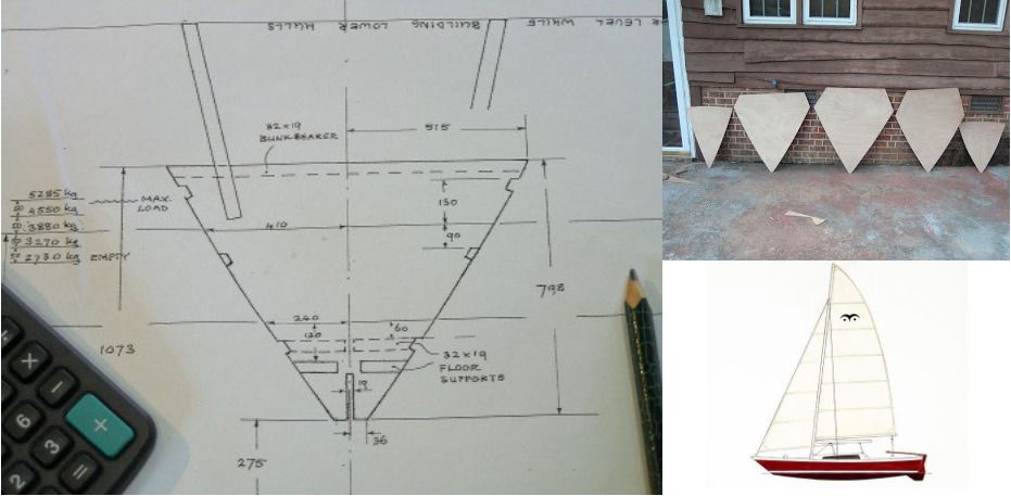
James Wharram designs catamarans meant to be cut from sheets of marine plywood with no rounded cross-sections, such as the Ariki shown here. Construction is simpler, but the midship coefficient is quite low.
The area of any ellipse divided by the area of the enclosed bounding box may be calculated as follows. The parametric equation for an ellipse is with ,

so the area of a quarter ellipse is
Dividing by the area of the circumscribing rectangle gives the ratio which holds for any ellipse. Stronger hulls with less wetted surface area arise from elliptical cross-sections, so we’ll assume for this design the hulls are elliptical, and set .
A boat’s displacement is the volume of water with a mass equal to the mass of the boat. The prismatic coefficient is defined as
where is the displacement. For catamarans, , and in this example, we’ve chosen . The prismatic coefficient for monohulls is usually in the range, . The prismatic coefficient is the ratio of the actual displacement to the displacement that would be generated if the maximum cross-section were extended to the length of the waterline. Lower values of favor boats in light air while higher values are better for boats at or above hull speed (discussed below).
The waterplane coefficient is the ratio of the area of the boat at the waterline to the product of the waterline beam, , times the waterline length, ,
where is the waterplane area. For catamarans, the waterline beam for the aft of the hull is almost equal to , and the forward third narrows towards the bow. Looking at the sketch below I guessed that the waterplane area in the aft portion is about 90% of the rectangle and maybe 33% in the forward section. This gives
Lucky guess! This is exactly the value Terho Halme chose for the example. Values for are typically between 0.69 and 0.72 for catamarans.

The final design parameter is the length to beam ratio, , which is the ratio of the overall length to the distance between hull centers or centerline beam,

A high value of means is small relative to the length and will reduce transverse stability, possibly leading to capsize. Low values mean that the boat will be wider and heavier, but able to carry more sail area. For this example, set .
Your SMath Studio worksheet should look something like this:

I also included two constants, the number of hulls and the density of seawater, .
# Derived Parameters
The remaining calculations are derived from these parameters and can be added to the worksheet somewhere below the design parameters. Many of them have been described already in terms of the design parameters.
When you add these equations to the worksheet include an equals sign “=” at the end to make SMath Studio immediately evaluate them.

The loaded displacement is calculated from the volume enclosed by the waterline length and beam times the draft, then scaled by prismatic and midship coefficients and multiplied by the density of seawater. This is the mass of water displaced by the boat sitting in the water which must equal the mass of the boat. Empty and light displacements are also calculated as 70% and 80% of the loaded displacement, respectively.
Transversal and longitudinal stability are indicators of how well the boat can right itself. Stability is the length of the righting moment arm, so a unit of meters is correct.
Since the purpose was to show why keeping track of units is important, let’s take a look at the last two calculations, engine power, and hull speed. Power should be in units of kilowatts and speed in knots, but instead, we get cubic meters and square root meters.
The first is easy to explain, and Halme says the engine power needed for a catamaran is about 4 KW / ton, which is the 4 in the equation. His equation for power is
and I assumed was for the density of seawater with units of . Instead, should be replaced with the conversion from to metric tons, . If we fix the equation we get
If you want to calculate sail areas, daggerboard, and rudder dimensions or estimate the speed under sail, see Basics of Boat Design or How to dimension a sailing catamaran? written by Terho Halme.
This still leaves the problem of the hull speed units.
# Froude Numbers
William Froude worked with Isambard Brunel on other engineering projects and had a minor role in the design of the Great Eastern. He realized that naval architects of the time had a poor understanding of engine power requirements and thought that by studying scale models of several ships he could get a better estimate of power requirements.
He built a towing tank at his home in Torquay, a seaside town in Devon, England, where he was able to measure the power required to pull the one, two, and four meter long models down the 100-meter tank. He found the ratio of the inertial force to the gravitational force remained constant as the scale dimensions changed, now called the Froude number,
Force is mass times acceleration (Newton’s Second Law of Motion). The units of force are in Newtons (), where . The gravitational force acting on a ship is the acceleration due to gravity, times the mass of the ship in .
In fluid mechanics, the inertial force is often written as
where is the density of the fluid and is a characteristic length defining the scale of the system and used to generate dimensionless quantities such as the Froude number. In this case, the characteristic length is the length of the ship. Now, is mass per unit volume times the volume of the characteristic length, , which becomes mass, and is velocity over time, or acceleration, . So, we could write this as
Froude’s number squared is then
Factoring out the mass and taking square roots,
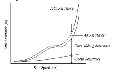
which is the usual representation. Froude also measured the drag, or viscous resistance, of a flat plate through the water. The dimensionless Reynolds number is the ratio of the inertial force to the viscous force and is used to estimate the viscous resistance. This plot shows the components forming the total resistance as a function of ship speed (from “Resistance and powering of ships”):
Now we can write the velocity in terms of the Froude number,
since . This means Halme’s hull speed of corresponds to a Froude number of .
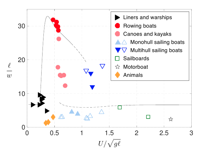
From Thin or bulky: optimal aspect ratios for ship hulls, by Boucher et al, the Froude number for multihull sailboats seems to cluster around , a bit higher than Halme’s estimate ( is the velocity):
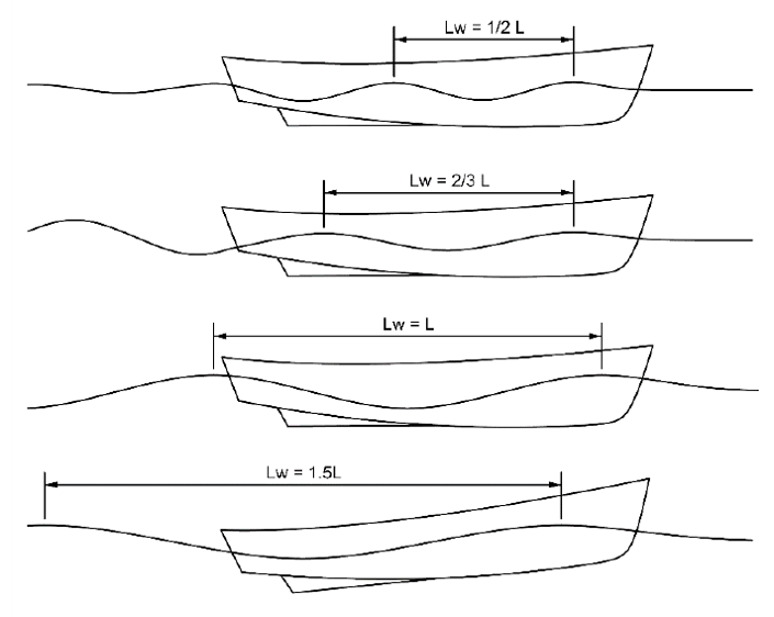
What’s so special about the hull speed? It’s the speed where the boat length matches the length of the wave generated by the bow. When this happens, the stern just catches up to the previous bow wave and can ride on it. Above this speed, the boat is always working uphill against the bow wave as can be seen here. This is why the characteristic length was chosen to be the length of the boat.
# Velociraptors
Mathematician and biologist D’Arcy Wentworth Thompson connected animal locomotion to Froude’s number when he realized the strength of leg muscles is proportional to the cross-section area of the bones. He compared the similarity of animals to ship propulsion,
“In two similar and closely related animals, as also in two steam engines, the law is bound to hold that the rate of working must tend to vary with the square of the linear dimensions, according to Froude’s Law of steamship comparison.”
Robert McNeill Alexander, Professor of Zoology at the University of Leeds compared the stride lengths of animals to hip heights to estimate bipedal running speeds. The hip height became the characteristic length in his equation,
where is the stride length and is the height of the hip above the ground for bipedal locomotion. This can be solved for the speed,
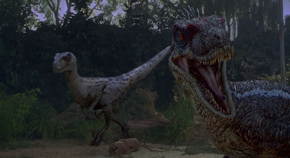
Alexander measured the stride length from dinosaur footprints and got the characteristic length from fossil bones and estimated the running speed of Tyrannosaurus Rex. Unlike what’s portrayed in the movie “Jurassic Park” Alexander concluded, “Tyrannosaurus was not good at chasing Jeeps.”
But, what about velociraptors? They will stalk you, hunt you down, and chew you to little bits. Is there any hope to outrun them?
Velociraptor stride lengths are usually about , and the hip height giving a velocity estimate of
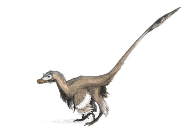
The stride lengths were taken from footprints where the velociraptor may have been walking, so running speeds could be a bit higher. In the movie, velociraptors were scaled up quite a lot as the actual animal was probably about the size of a turkey and may have been more like this, um, vicious-looking dinosaur:
# Walking on the Moon
The velocity estimate depends on the gravitational acceleration constant which is on Earth, but on the Moon, the force of gravity is about 16% of Earth’s gravity, so the velocity becomes
The Apollo astronauts found that attempting to walk at normal terrestrial speeds on the Moon was quite difficult and wound up skipping instead. Even though gravity is reduced on the Moon, their walking speed and stride length didn’t match what they were used to on Earth. A more complete description of the connection between the Froude number and walking and running speeds can be found in the paper by Vaughn and O’Malley, “Froude and the contribution of naval architecture to our understanding of bipedal locomotion.”
William Froude’s experiments show that a boat’s hull speed, the length of a velociraptor’s stride, and the effects of the gravitational field on the Moon are all related.